
A mechanical drawing showing where the PEPI crates are located is shown below.
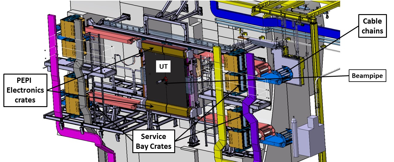
The Periphery Electronics Processing Interface (PEPI) design and development has been carried out by our collaborators at the University of Maryland. The PEPI electronics provide the interface to acquire and send signals to/from the UT stave to/from the LHCb DAQ. There are 8 PEPI boxes (4 in front and 4 in back of UT(not seen in figure above)).
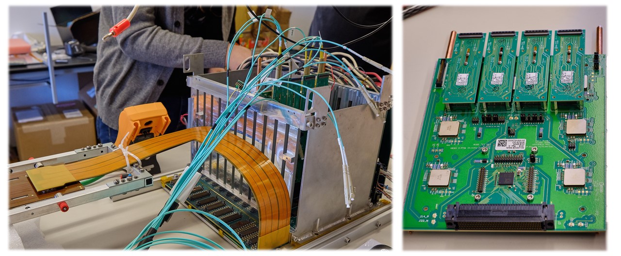
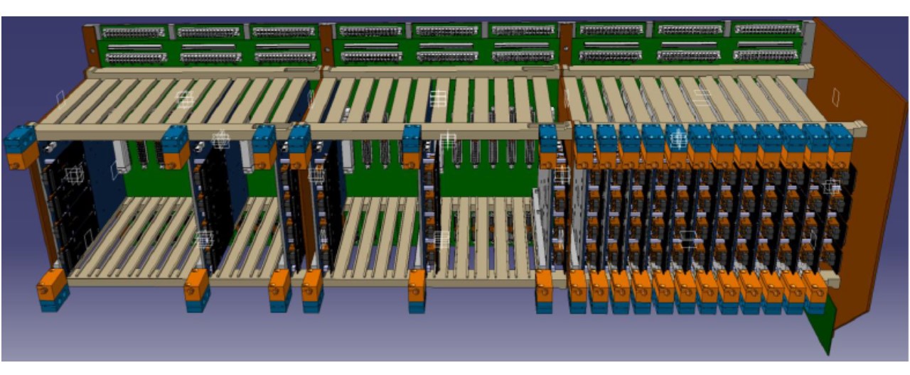 Each PEPI box contains 3 separate backplanes as shown in the figure above. Each backplane is an ultra-dense, 28-layer circuit board that is used to route the signals and power to different boards that are plugged into the backplane. A photo of a single backplane is shown below.
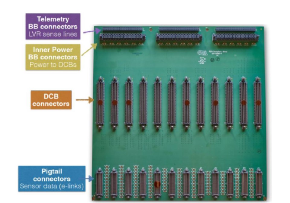
As shown in the figure, there are four connector fields:
- Pigtail connectors: This is where the pigtails from the stave are connected.
- DCB connector: The DCB board plugs in here and is the main board that serializes the data and send it to the LHCb DAQ. The DCB also has other functions, including monitoring of electronics temperatures, configuring and sending clock to the SALT chips , and performing a reset of the SALT chip if/when necessary.
- Inner Power breakout board connector: A board plugs into here that takes low voltage power sent from the SBCs, and routes it to the pigtail connectors.
- Telemetry breakout board connector: The telemetry board is designed for transmitting operating voltage and temperature information of the UT to boards at the SBC and then to the main ECS control system of LHCb.