A number of design considerations were taken into account when designing the Upstream Tracker (UT). These include:
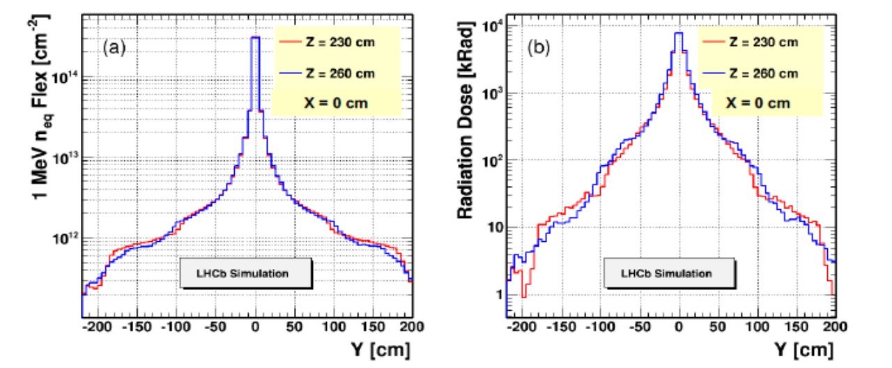
- All components need to be able to withstand the large level of expected irradiation expected during Run 3 and Run 4, which is ~3×10¹⁴ neq/cm2 (see radiation fluence maps below); accordingly, the silicon sensors must be kept below -5 C.
- The UT must not have any gaps in the acceptance for particles produced at the PV, and have lose to 100% acceptance for long-lived strange particles decaying upstream of the UT;
- The innermost silicon sensor should come as close to the beam pipe as possible; sensors with a circular cutout for the innermost sensors would allow us to get within about 1-2 mm of the beam pipe.
- The efficiency of obtaining at least 3 hits on a track within the UT acceptance must be > 99%.
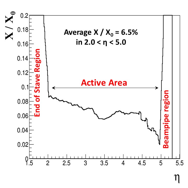
- The material must be kept to a minimum. The current material map for the UT indicates about 6% of a radiation length, on average, for tracks within the UT acceptance (see figure below).
- The detector must be read out at 40 MHz, so that UT hits can be used at the first level of the software trigger;
- The occupancy should be at the percent level or less, to provide fast pattern recognition capabilities with low rates of “fake” tracks;
Radiation map of (left) fluence as a function of Y at X=0, Z=230, 260 cm, and (right) dose in kRad. These maps do not include the usual safety factor of 2.
The plot below shows the fractional radiation length as a function of pseudorapidity, for a track traversing the UT detector. Here, η=-log(tan(θ/2)), where θ is the angle with respect to the beam axis. Within the UT acceptance (about 2≤η≤5), the average radiation length is about 6.5%. The slope as one moves toward small η is due to an increase in the number of copper traces in the flex cable as one approaches the end of stave.