 Outside of the unique facility at CERN, our group has several laboratories in the Physics Building, which enable our detector R&D program. Here, we show some of our facilities and equipment at Syracuse.
Rm 304: Much of the UT module construction and testing occurs in Rm 304. UT modules are kept and handled only in cleanroom areas. Rm 304 has two cleanrooms and an open area. Photos of the spaces are shown in the photos below.
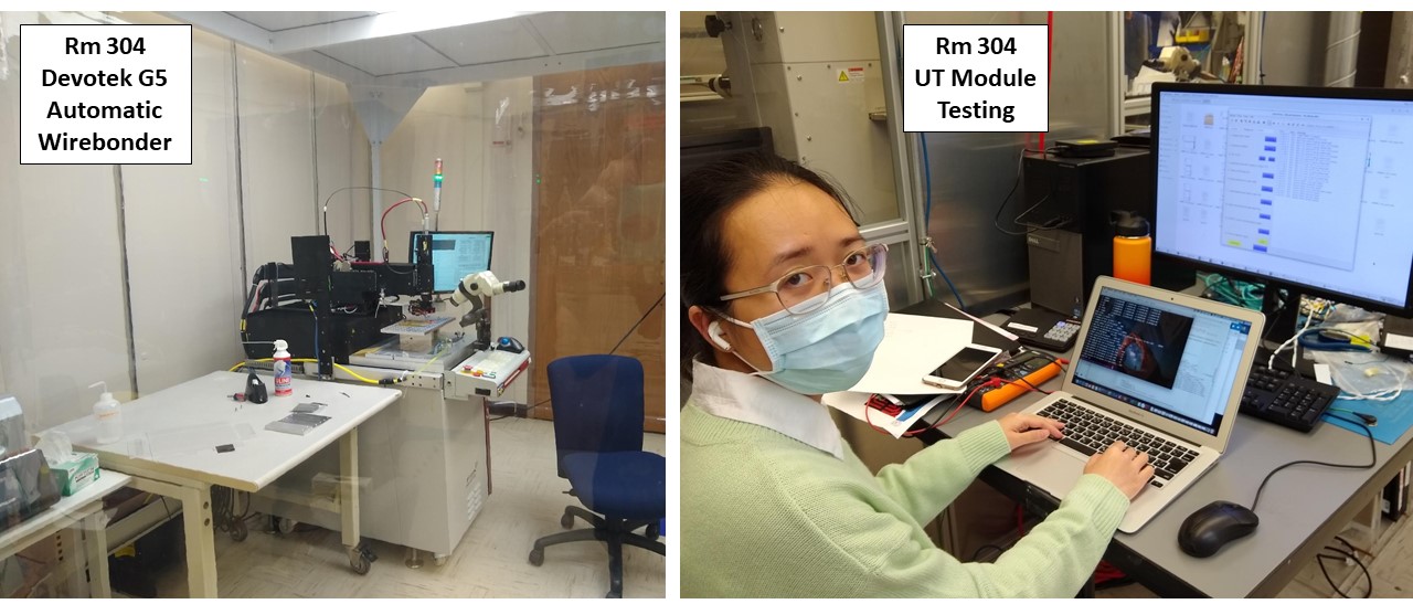 Above, we see the cleanroom built around the Devotek G5 automatic wirebonder, used for wirebonding the hybrid to the sensor. On the right, is student Hang Pham, who is part of the team testing UT modules electrical performance. She is running the DAQ, which is outside the clean area, while the modules are inside the cleanroom (see photos below).
Below, are photos of (left) graduate students Baska and Xixin testing the UT modules. Hang Pham is on the other side of the wall to the right. Also seen is the pull tester, which allows us to ensure that the wirebonds are of high strength. To the right of the pull tester is a glue robot (not seen); (middle) a photo showing the Devotek G4 automatic wirebonder used for wirebonding hybrids to sensors, and hybrids to the data flex on the stave; and (right) station where module gluing occurs, at the far end of the cleanroom.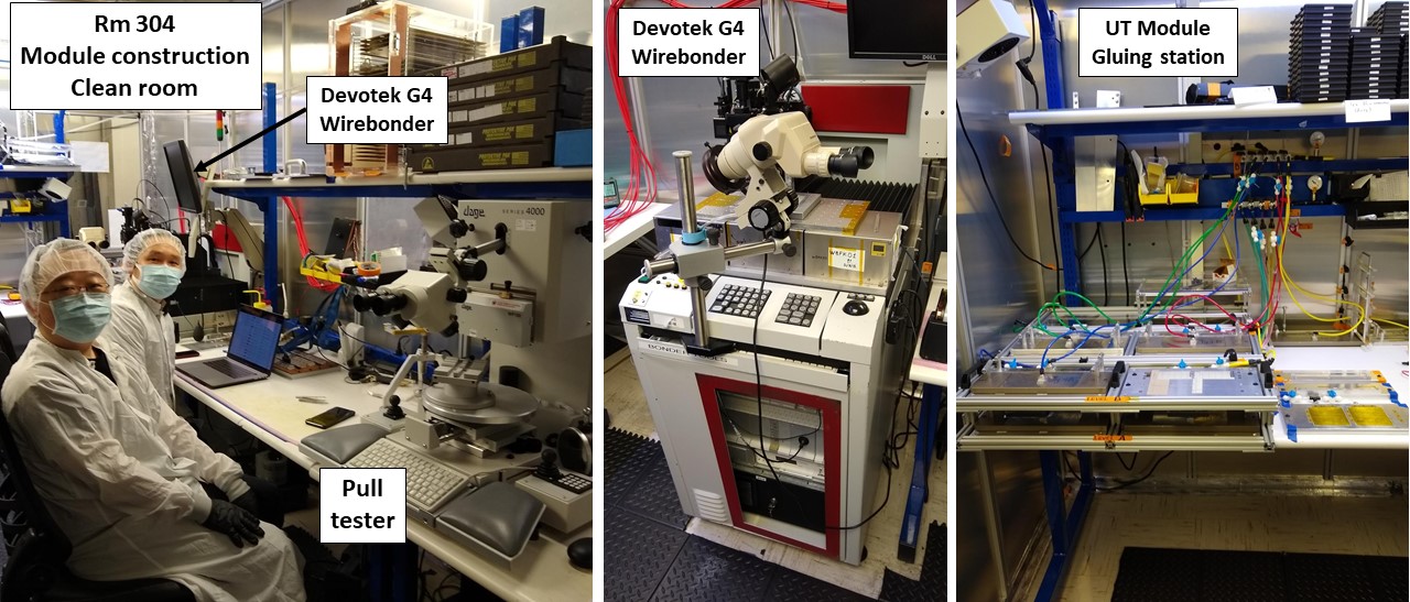
Rm 306: After modules are constructed, they are stored, and eventually mounted onto staves in our Rm 306 cleanroom. Below, we show (left) a photo of Rm 306, where the uninstumented staves have been constructed and are stored. As that process has been completed, the granite tables (2) are used for mounting/gluing the UT modules onto staves. Once the glue is cured, the stave is carefully brought back to the Rm 304 cleanroom, where each module is wirebonded to the data flex cable.
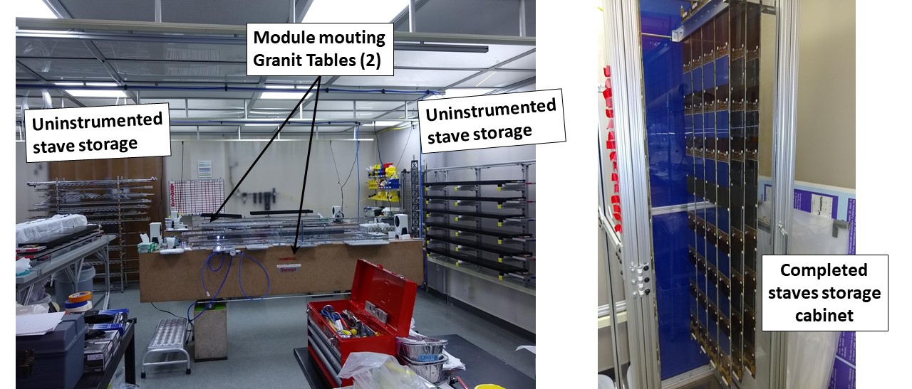 After the wirebonding is completed, it is possible to read the stave out through the connector at the end of the stave. A second MiniDAQ system [that is connected to the stave by a pigtail cable] is used to test each module on the stave (also done in Rm 304 cleanroom). After this test, the stave is returned back to Rm 306 where they are stored in a cabinet (see photo above to the right).
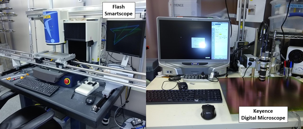
Also in Rm 306 is a Flash Smartcope (see photo left below) which is used to precisely measure the positions of the sensors along a stave. The stave is mounted on, and guided by the rail system shown. On the right is shown a Keyence Digital Microscope (also in Rm 306) which gives high magnification and quality images for visual inspections of the UT components.
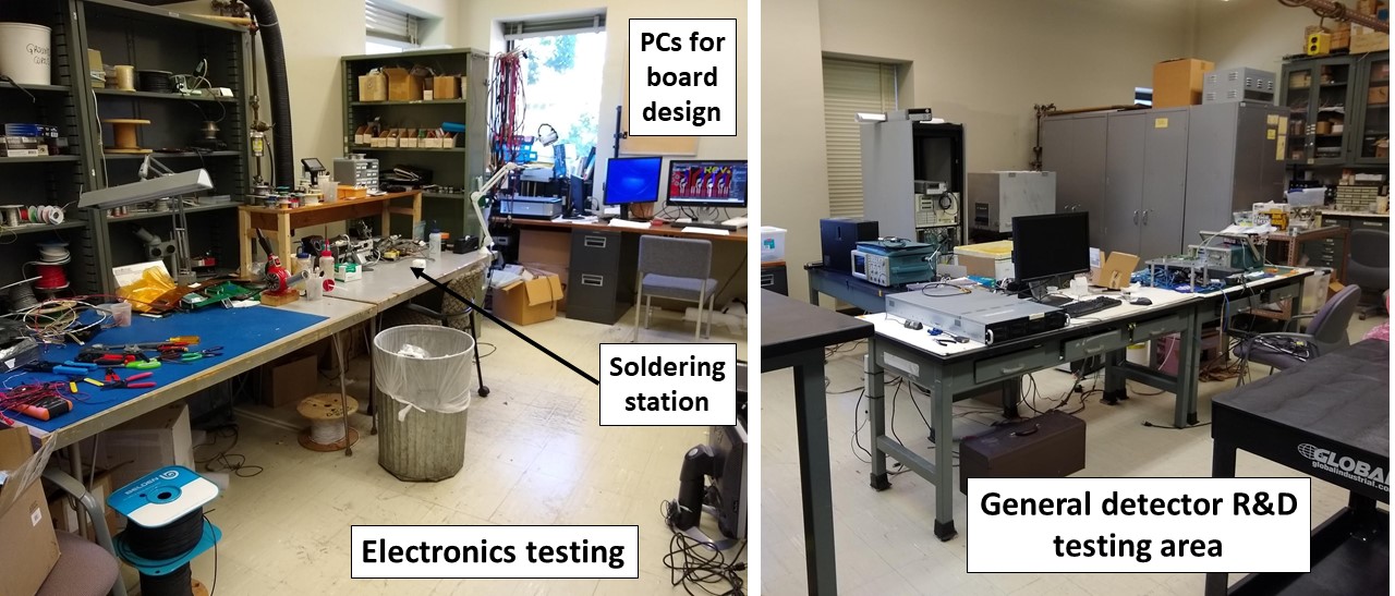
Rm 335: This is a large general-use (non-cleanroom) lab space . It is used for various activities, such as soldering, electrical testing, building components, temperature-cycling components. There are also PCs in the lab for designing electronics boards. The photo below shows (left) the area for electrical board work, which includes a solder station, and various tools to work on electronics boards, and (right) a general purpose area used for a variety of R&D activities.
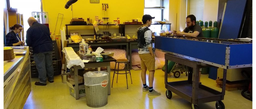
Rm 343: This is another general purpose area for detector development. Currently it is being used to build the transport boxes that are used to ship the staves to CERN. Also, there is an area (table in center) dedicates to cleaning mechanical parts before they are used in the construction. Shown are (right) graduate students Joe Shupperd and Vincent Musso, and to the left is first year student Bridget Mack working with Prof. Ray Mountain.
B235: In the sub-basement, we have another laboratory space with a dedicated clean room area (see photo left below). Upon entering, there is a gowning area, and the control PC. Beyond that there is a clean area, which contains a second Flash Smartscope (see photo right), which is used to scan the silicon sensors in an automated way, and find any scratches or defects on the surface. It is also used in other tasks as well, when needed.
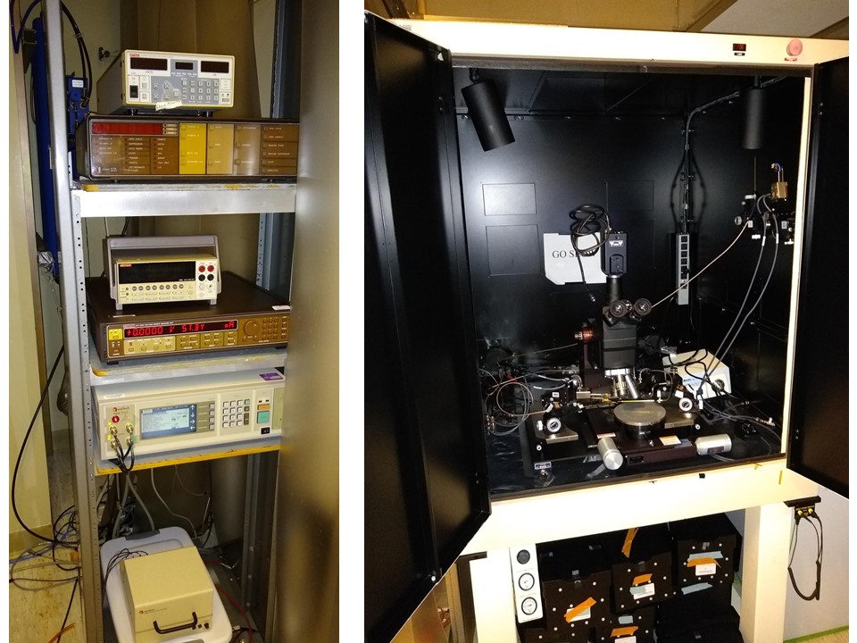
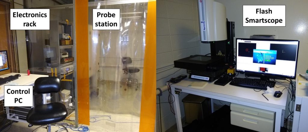 In addition, B235 cleanroom includes a probe station (right, below) and electronics rack (left, below). The probe station includes a microscope and ultra-fine probe tips for making the electrical contact with the sensor pads. The probe tips allow are connected to various instruments contained in the electronics rack (see left photo) for the measurements, which are in turn connected to the PC(photo above).