
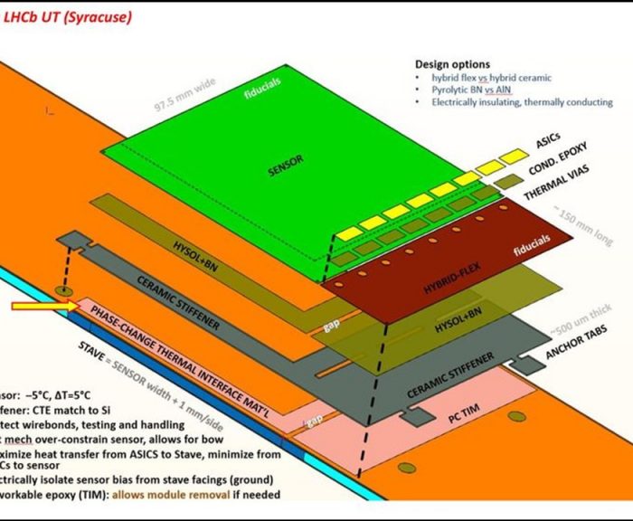
The module consists of the silicon sensor, an electronics hybrid, and a pyrolitic boron-nitride (PBN) ceramic stiffener, as shown in the exploded cartoon above. The sensor is approximately 10 cm x 10 cm x 0.25 mm, and is described in more detail here. The hybrid, designed by INFN Milano, provides the electronic interconnections to and from the SALT ASICs, and includes routing of the bias voltage to the sensor along with local filtering.
The SALT ASIC is a custom chip designed for the UT by our collaborators at AGH Krakow. The ASICs are glued to the hybrid using electrically conducting epoxy. Briefly, the SALT ASIC features 128 channels, which amplify and shape signals from the silicon sensor, subtracts the channel-dependent pedestal, followed by the subtraction of an event-by-event common-mode noise. In normal “zero-suppression” mode, the ASIC transmits information on only the hits that are above a programmable threshold. More information on the SALT ASIC can be found here.
It is imperative that sensors receiving high radiation fluence be kept cold, below about -5 C . The largest contribution to the heat budget is from the SALT ASICs (~0.5 W/ASIC). The heat is removed by conduction through the PBN stiffener to the stave, which is kept cold using a bi-phase evaporative CO2 cooling system. The stiffeners are about 0.5 mm thick and are thermally conductive, but electrically insulating. The stiffener is attached to the stave using an epoxy/thermal interface material that allows the module to be removed in case in case it ever fails. Stronger hysol glue is used under the anchor tabs to ensure that the module makes a rigid connection to the stave. If the module needs to be replaced, it is understood that the anchor tabs will break off when the module is removed, and they remain on the stave.
The major steps for building a module include:
- Visual inspection and electrical testing of hybrids in their panel. Only hybrids with >99% good channels are accepted.
- Gluing of the sensor and hybrid to the PBN stiffener
- Wirebonding sensor channels to inputs of SALT ASIC, and HV/HVret on sensor to corresponding hybrid pads
- Electrical testing of hybrid (dead/noisy channels) as well as check for normal current-voltage (IV) behavior
- Potting of wirebonds using Sylgard encapsulant
- Retest of module for normal sensor IV and check for dead/noisy channels on SALT ASICs.
- Connectors cut off
- Final visual inspection
- Modules glued to stave
- Hybrid wirebonded to stave flex cable
- Final electrical testing of each module on stave (sensor and SALT ASICs)
- Smartscope survey of the positions of each module.
At each point in the production, component information is stored and updated in the UT Database. Click on any image below to get an enlarged version.
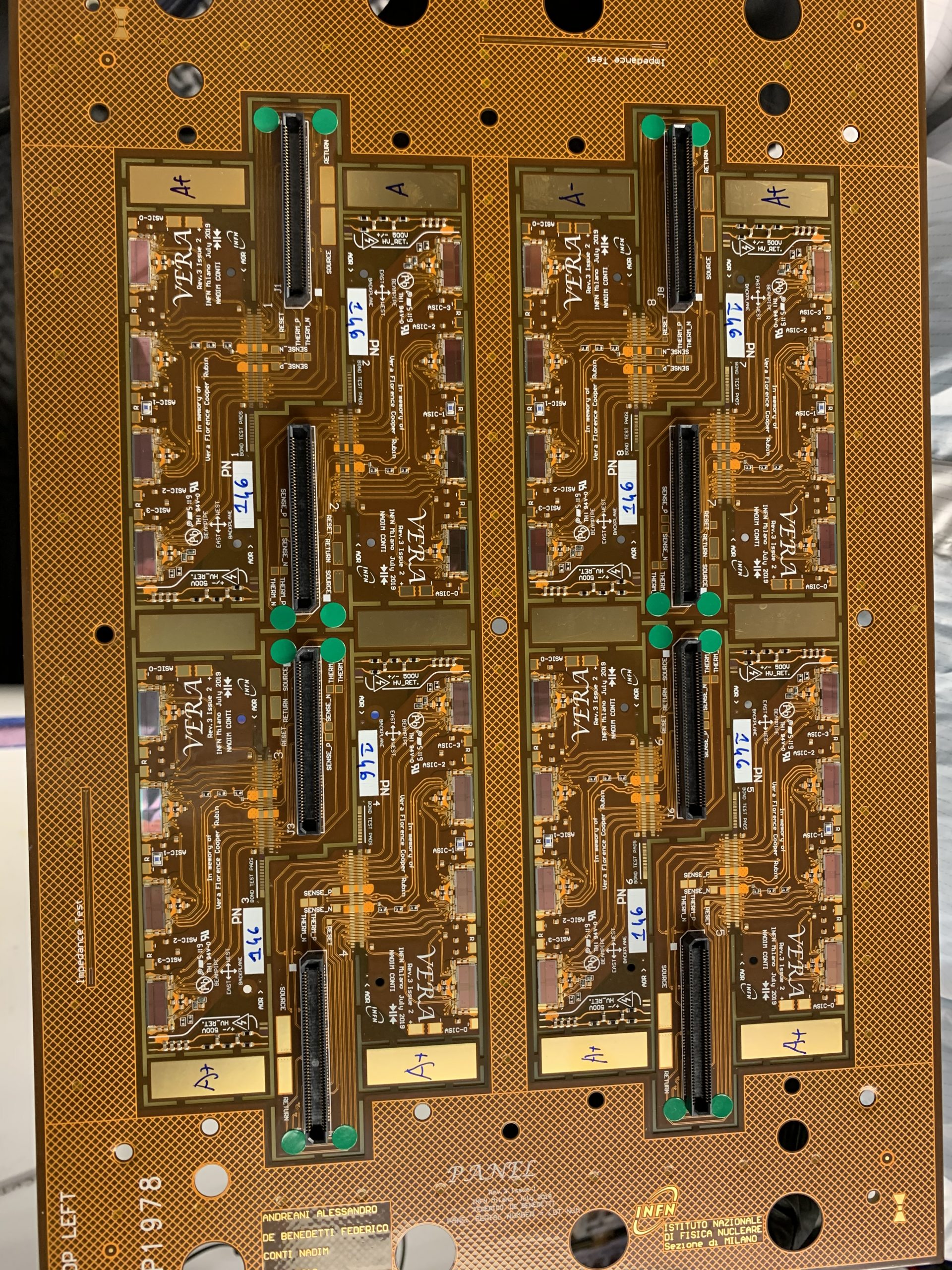
The photo to the left shows a panel (produced by INFN Milano) that has arrived at Syracuse. The panel contains eight 4-chip hybrids, and each one has a connector to control and read information from the SALT ASICs. The hybrids are held in place with tabs that can be cut once the hybrid is ready to be removed. The panels are burned in & tested at Milano before shipping to Syracuse. Upon arrival at Syracuse, each hybrid is visually inspected and electrically tested before removal (tabs are cut) from the panel.

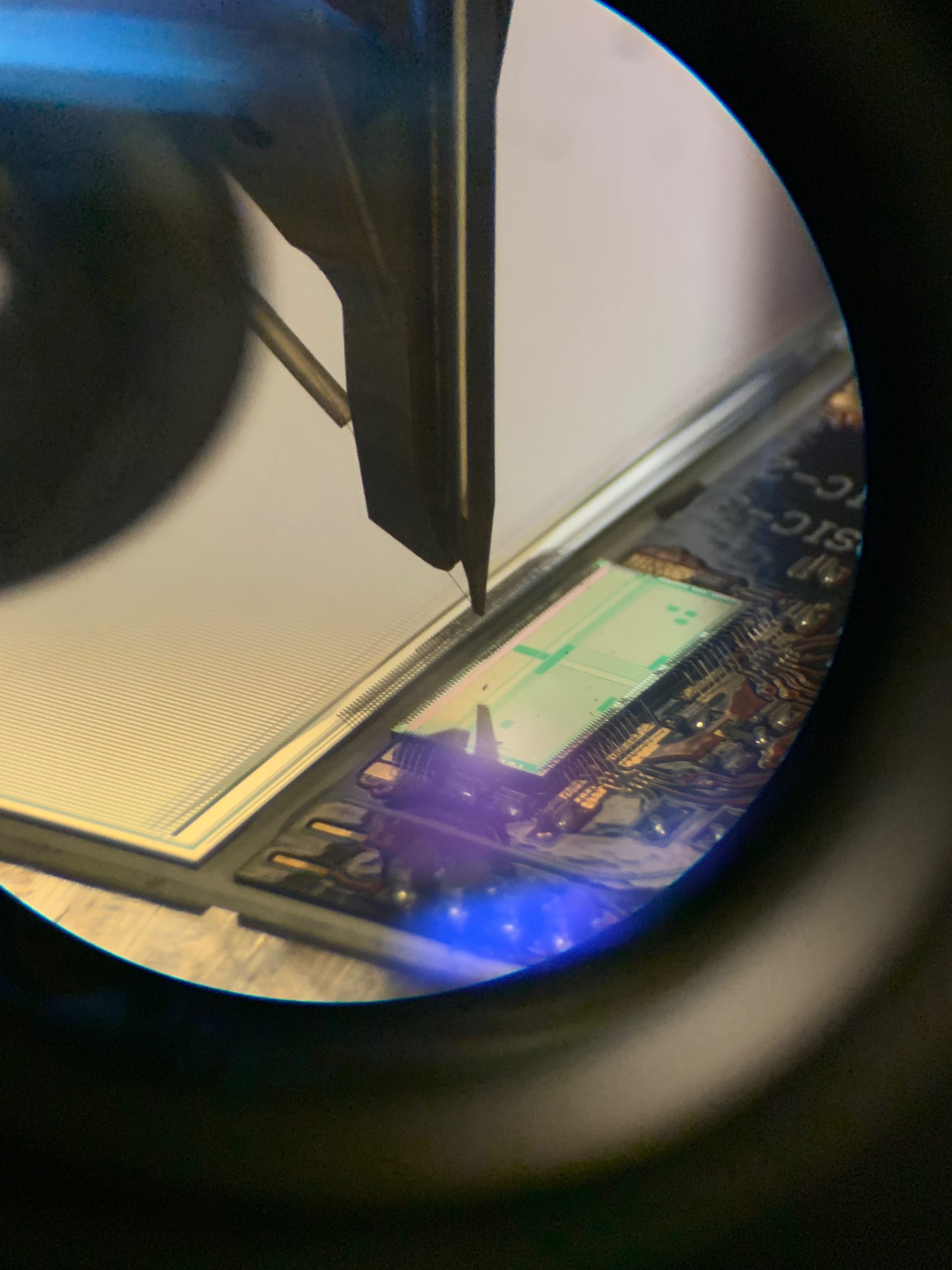
The figure to the left shows a closeup image of one SALT ASIC, taken during the visual inspection at Syracuse. The front-end of the ASIC is at the top edge and the control lines are primarily at the back (bottom in figure). The wirebonds to the hybrid can also be seen. The visual inspection looks for (1) scratches on any pads, (2) excessive residue, (3) mishaped or broken wirebonds, (4) excessive glue, and (5) any apparent damage to ASIC or hybrid.
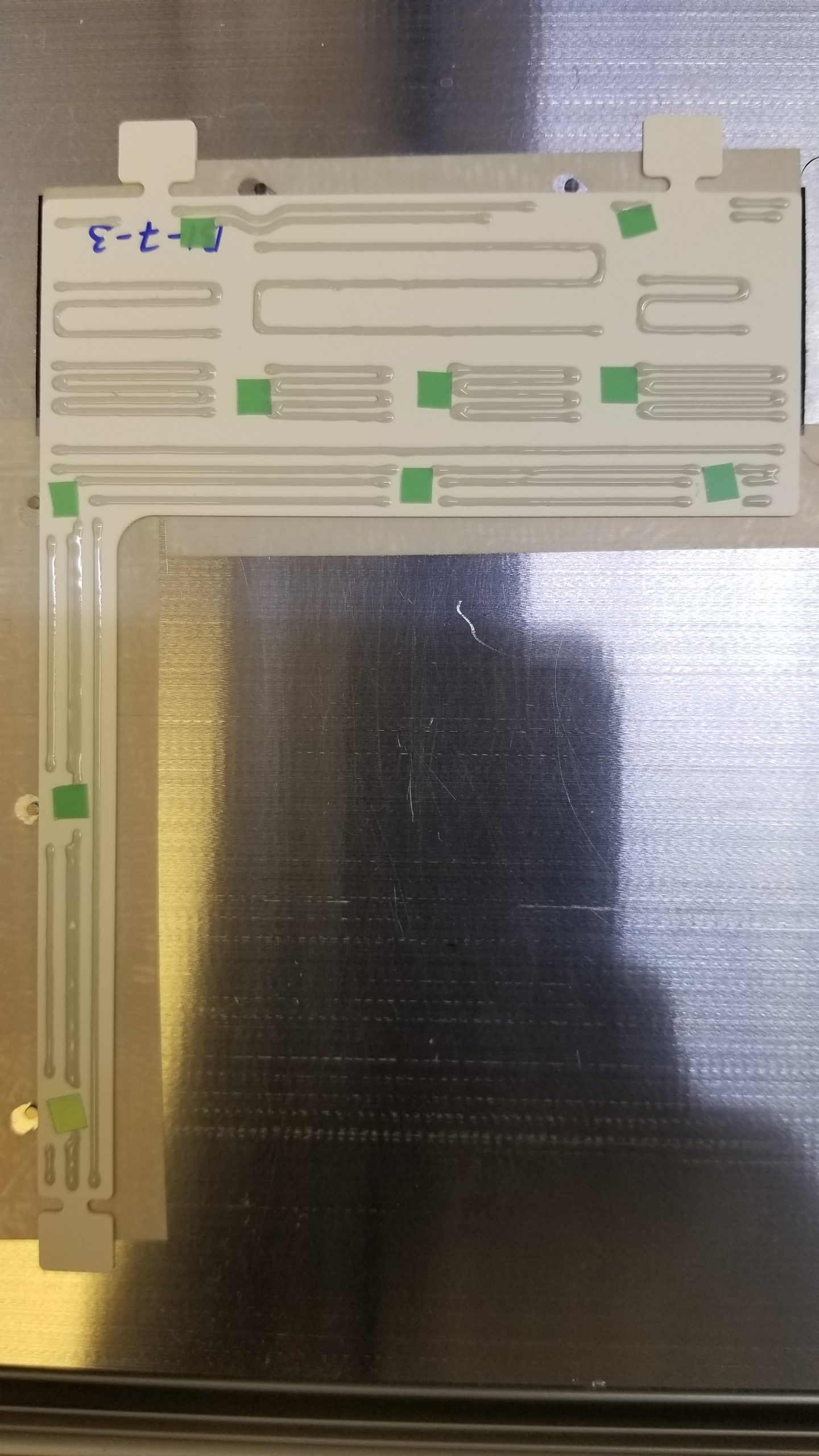
Modules are formed by gluing a hybrid and a sensor to a PBN stiffener using a set of precision jigs. A programmable glue robot is used to deposit a controlled amount of glue (hysol with diamond powder) onto the PBN stiffener with a well-defined pattern. The pattern is intended to give good glue coverage under the ASICs (for heat transfer purposes), and along the top and bottom edges where wirebonds will be made (for stability). The remainder is sufficient to give good adhesion to the hybrid and sensor. It is also important that the glue not ooze out the side, as this could lead to difficulty in removing the module from its jig. The green tabs are spacers to ensure that the glue thickness between the PBN stiffener and the sensor (or hybrid) is no less than 50 um. Due to increasing viscosity of the glue versus time, the pressure and time are calibrated in order to give the correct amount of glue. Precision vacuum jigs are then used to place the sensor and hybrid onto the stiffener, and the glue is allowed to cure overnight. The modules are then removed from the jig the next day.
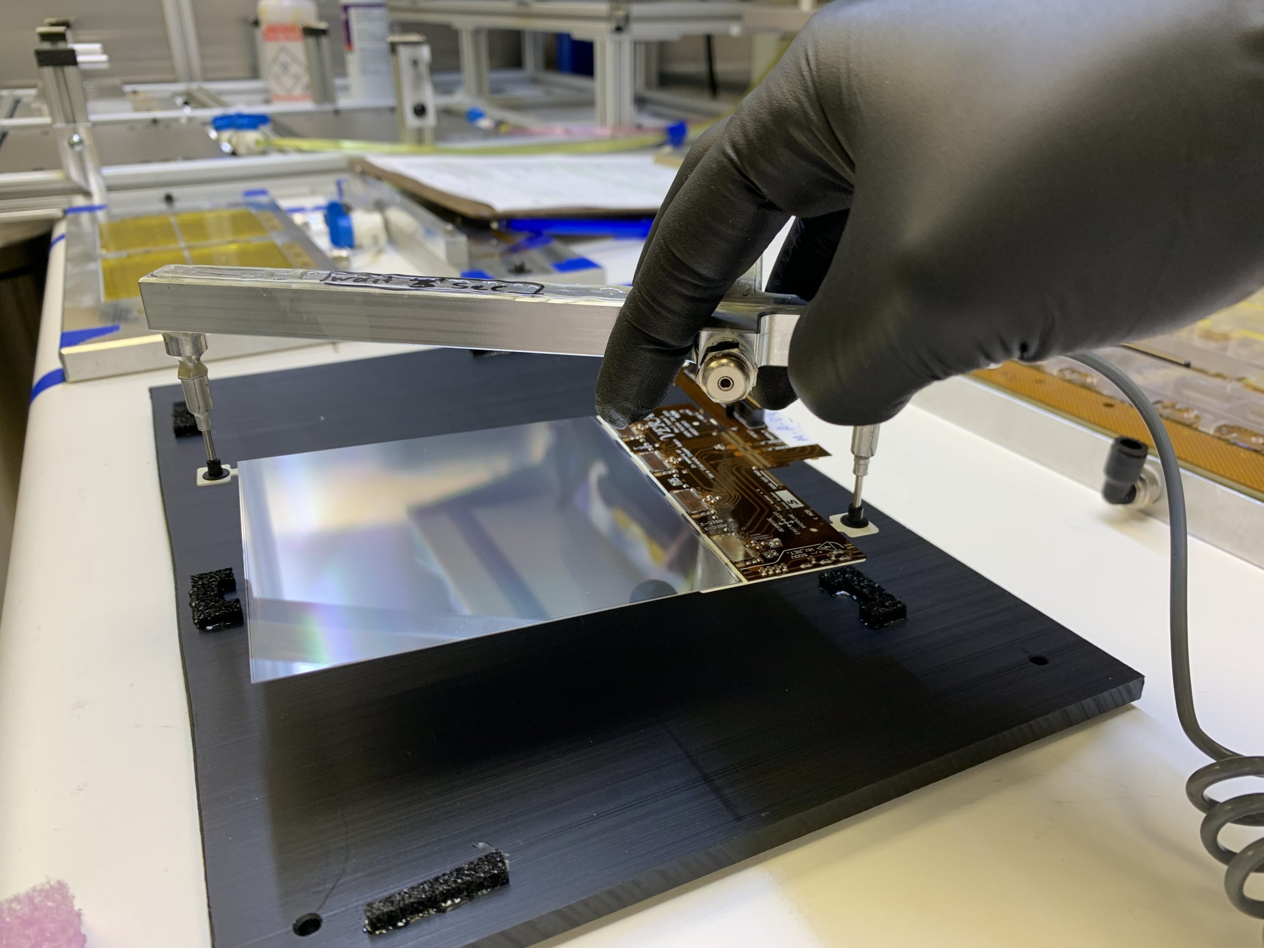
The modules are very delicate, both mechanically, and electrically. Custom designed vacuum pickup tools are aligned to the anchor tabs on the PBN stiffener for moving the module. In addition, strict ESD protocols are followed when handling modules. Handlers use ESD gloves and ground bracelets, and deionizing fans are used in the cleanroom to minimize static charge buildup.
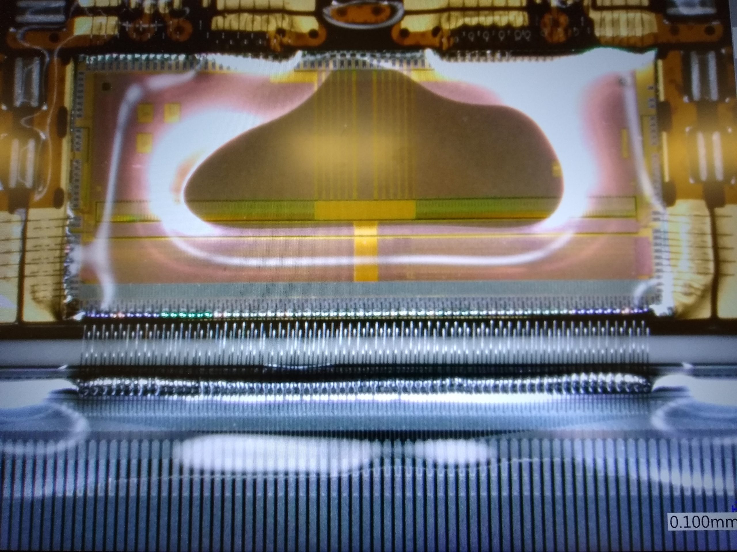
After the sensor and hybrid are glued to the PBN stiffener, the 512 (or 1024) sensor channels are wirebonded to the front-end inputs of the SALT ASICs. This is accomplished using an programmable wirebonder (Devotek G4 and G5). In addition, two wirebonds are made between the sensor bias and return pads on the sensor to the corresponding pads on the hybrid.
After wirebonding and subsequent electrical testing, the wirebonds are potted using the glue robot. Potting of the feet on both ends of the wirebond prevent possible corrosion of the wirebonds, and also provide resilience against mechanical vibrations.
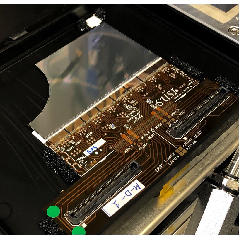
Below, we show a Type D module. The 1/4-circle cutout is to match the contour of the beam pipe for the innermost sensors.
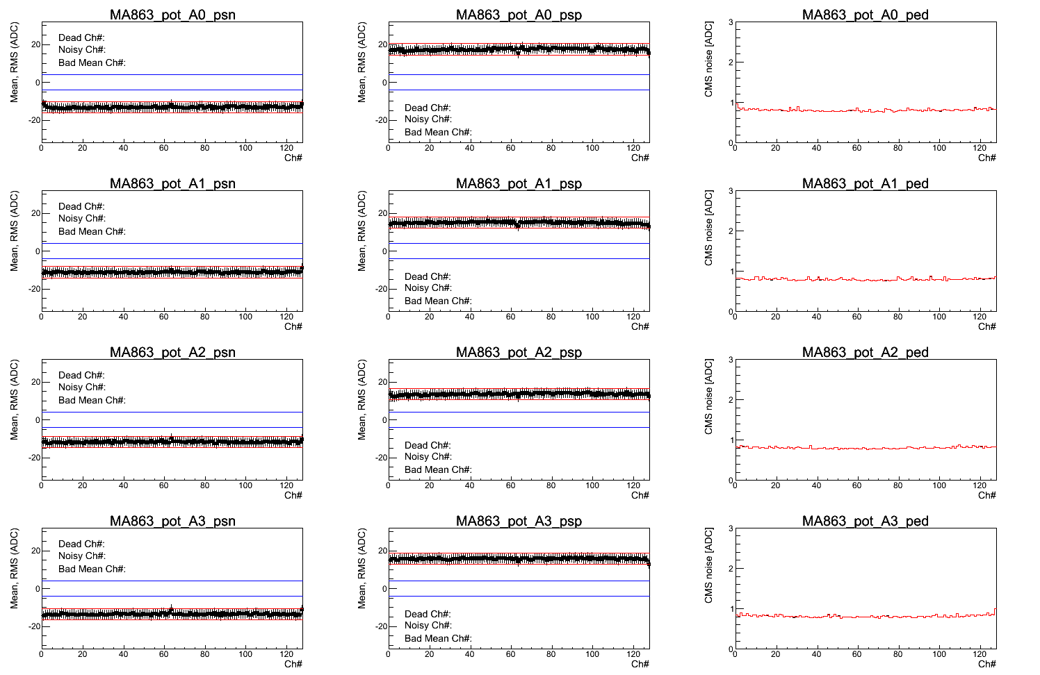
The plots below show a summary of electrical test results of a good module after potting. The first (second) column shows the response of each of channel of the four ASICs to a negative (positive) charge injection. The third column shows the common-mode subtracted noise versus channel number. The noise level is about 0.85 ADC counts, whereas a signal from a minimum-ionizing particle is 12-13 ADC counts.
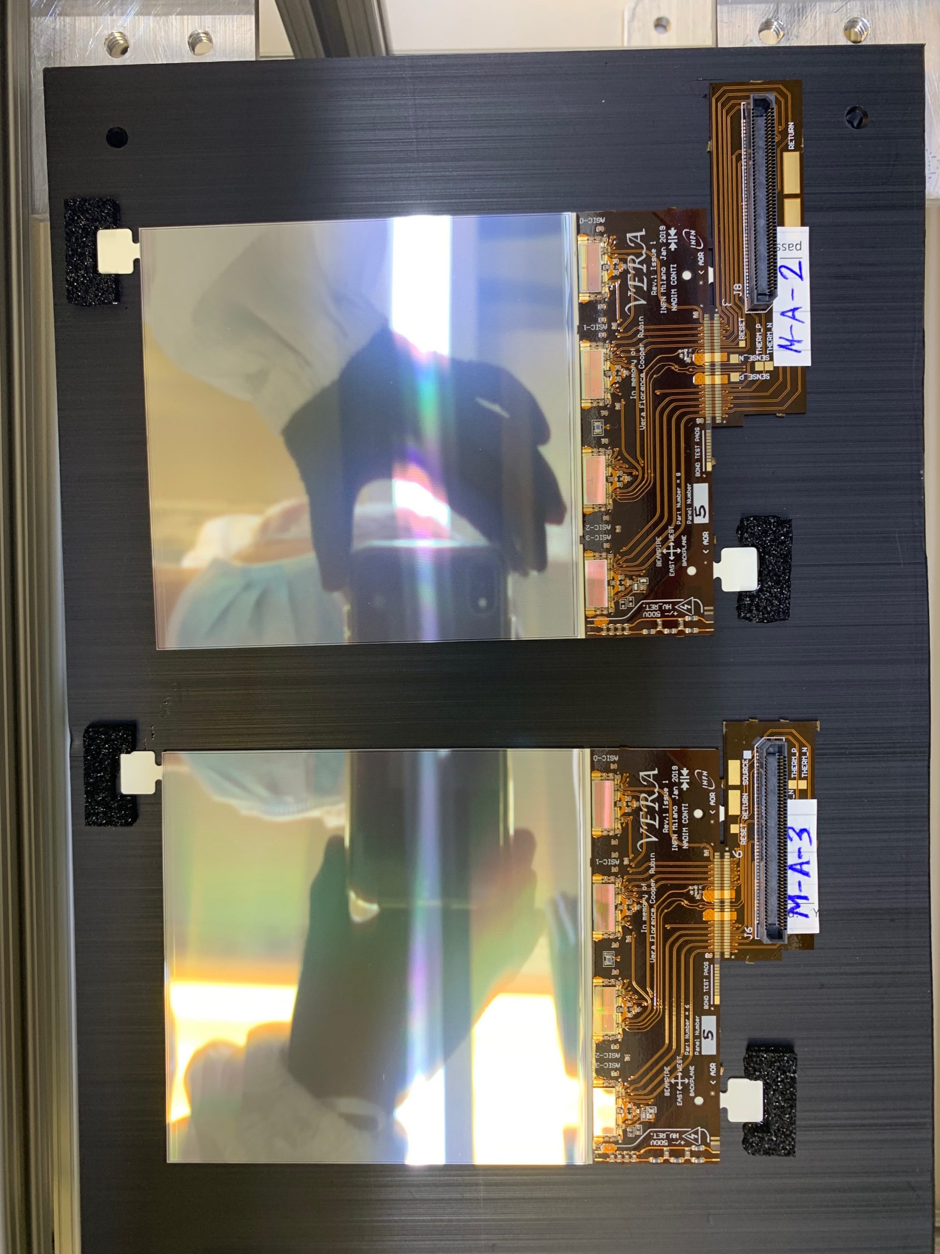
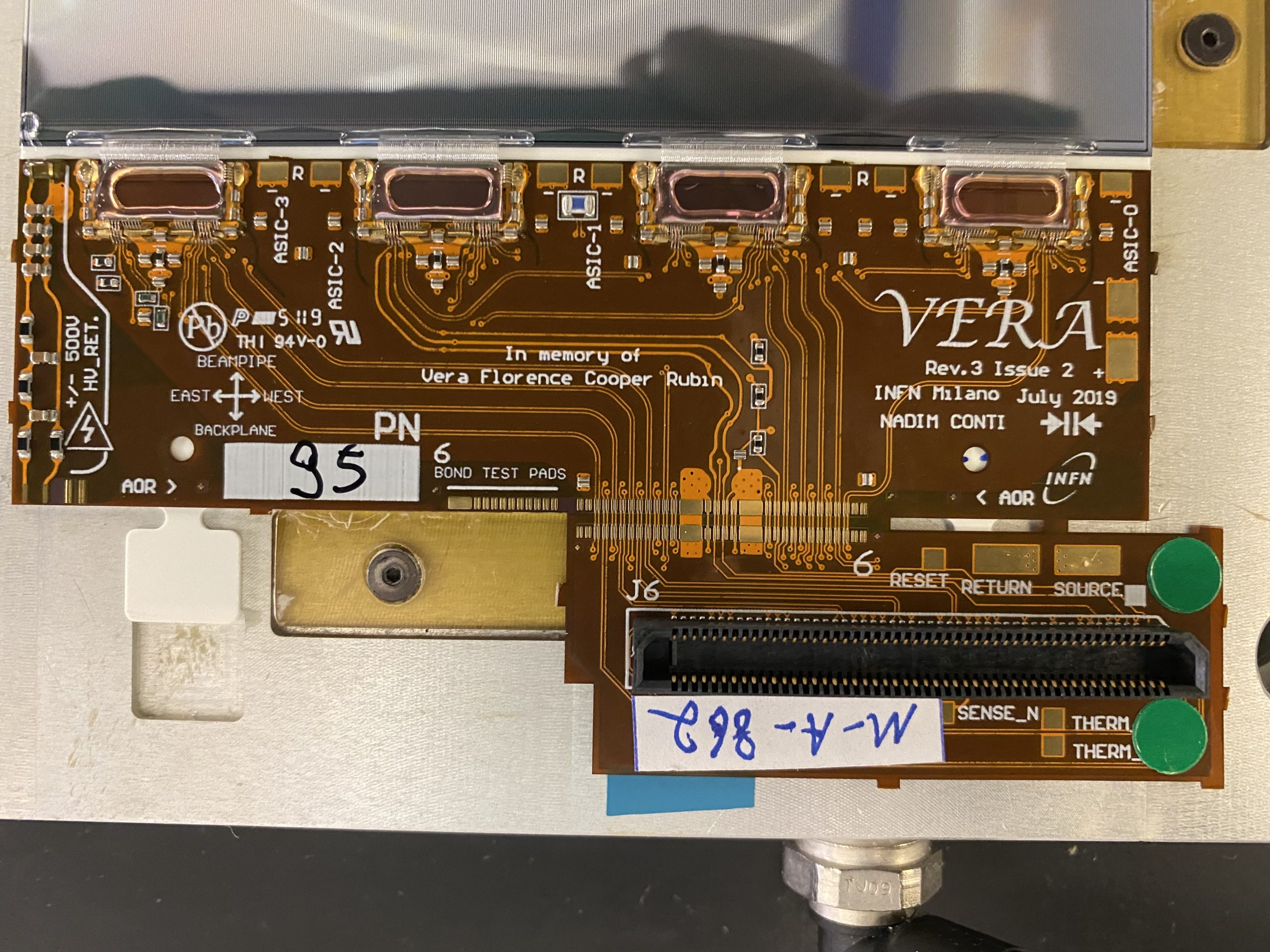
A photo of a pair of 4-chip modules is shown to the left. On the right side of the figure are the connectors that allow the modules to be electrically tested during the course of the assembly. Only just before they are to be mounted on a stave are the connectors cut off.
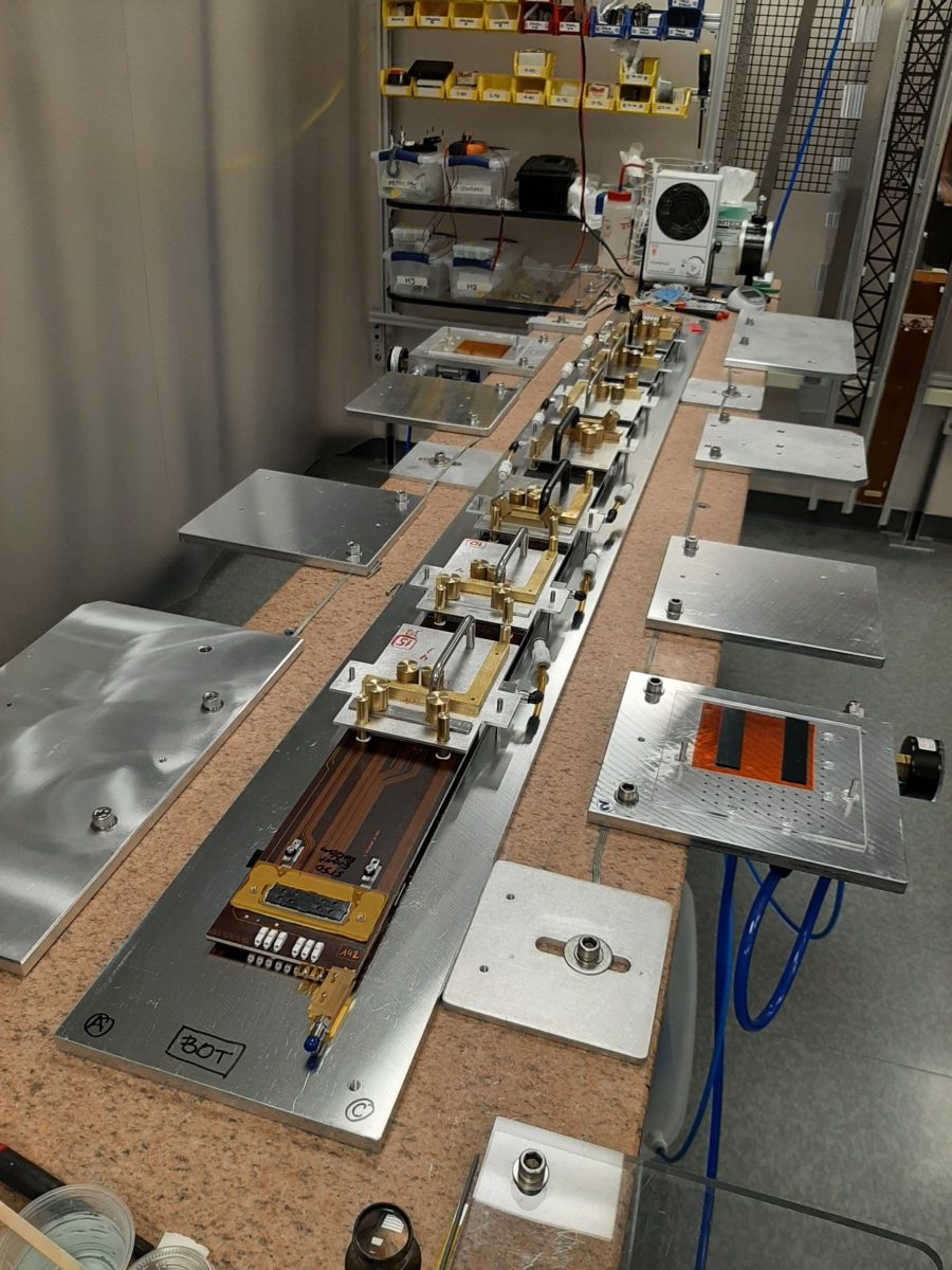
Photo showing 7 modules being mounted on one side of a stave in Rm 306 cleanroom at Syracuse. The modules are placed using precision pins to ensure that the modules are placed in the intended location with about 50 um precision.

Photo showing two modules mounted on a stave. Between the two modules is a gap, where only the flex cable is seen. As the staves are double-sides, there are additional modules on the back that cover the gap regions on the top side. Front and back sensors are also overlapped by about 2 mm to facilitate alignment.
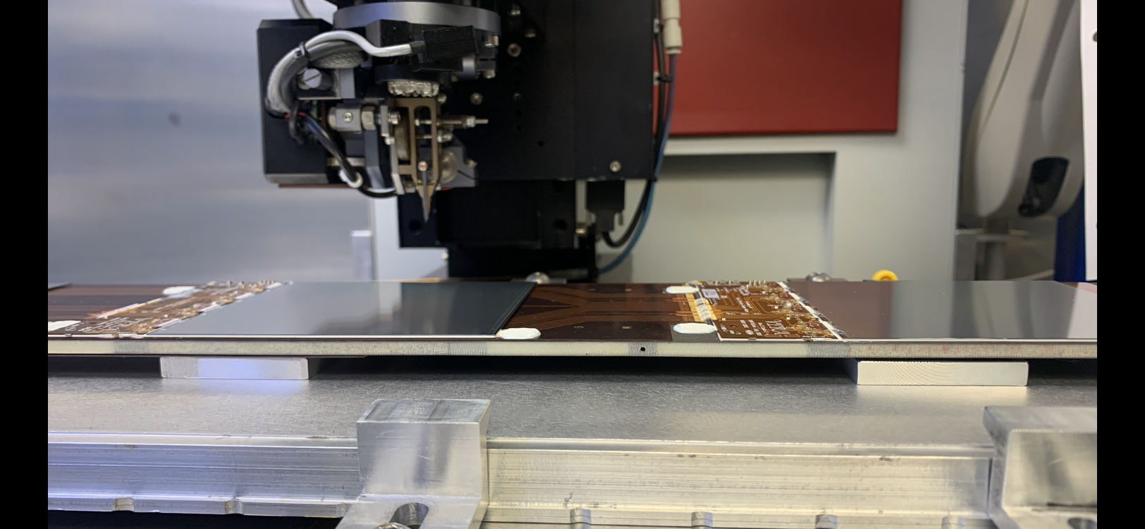
After the module is glued to the stave, the hybrid needs to be electrically connected to the flex cable on the stave. The flex cable carries the signals from the periphery of the UT to/from the modules, as well as the sensor bias and return. The photo shows a portion of the stave where part of two modules is seen. On the left is the silicon sensor from one module, followed by a gap , and then the hybrid of the second module. In the “gap” region, one sees the flex cable, which runs underneath the modules. The staves are double-sided, so in the “gap” between the two modules on the top, there is a silicon sensor underneath (not visible in the photo).
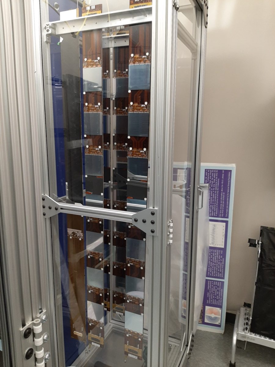
Completed staves hanging vertically in a storage cabinet in Rm 306 cleanroom.
More coming …